Goal Zero Electrical
As written on Ford Transit USA Forum
This is not professional advice only an account of what I have done. Knarly Vans LLC will not be held liable for any actions caused by following these accounts. Use this information responsibly and always consult a professional.


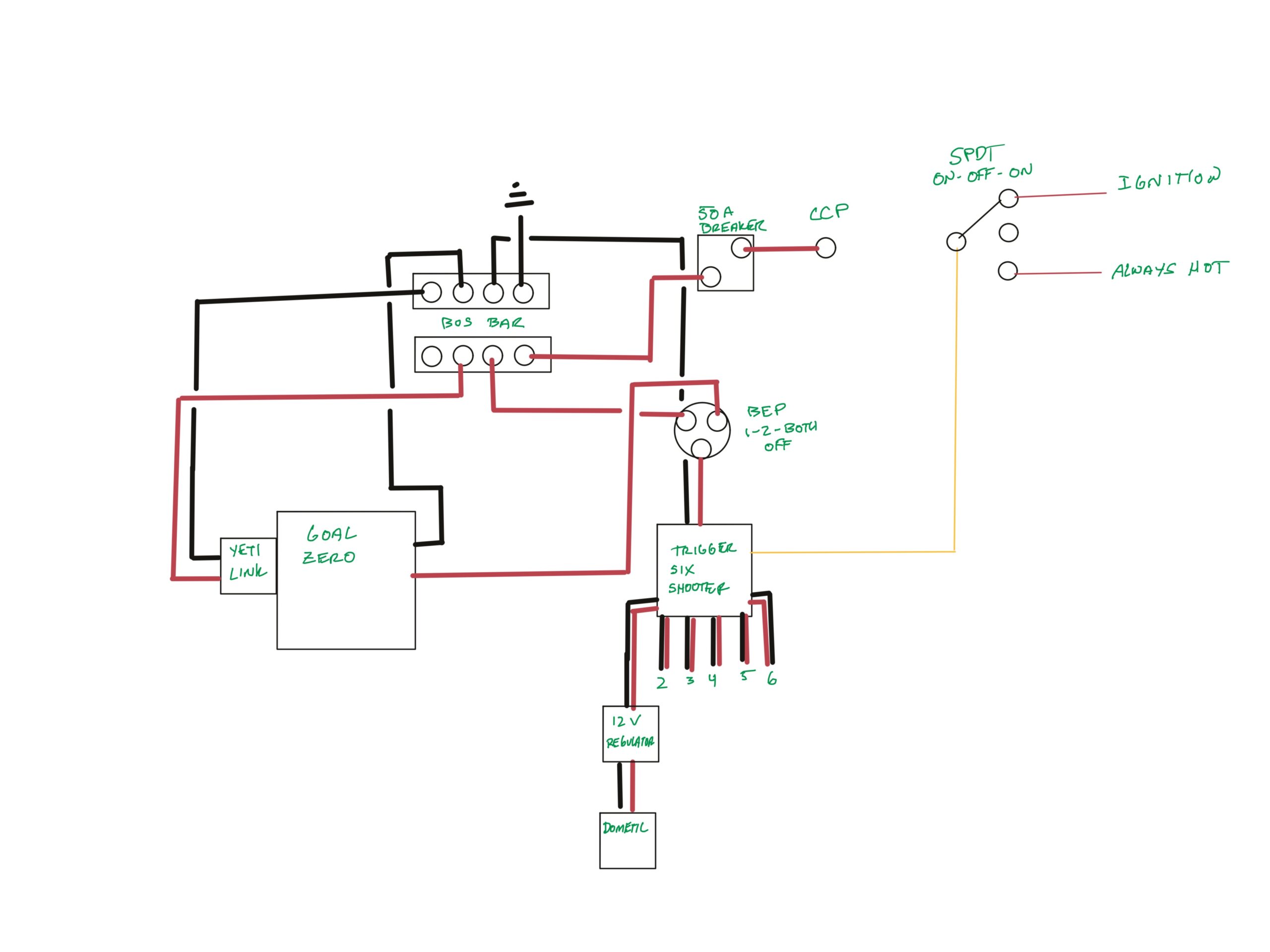
It took a couple weeks to hear from Goal Zero, however they came back and said that if the unit ends up charging itself it won’t ruin anything. With that I put together my power center. I added Hein’s SPDT dash switch and tapped some fuses for power (horn and heated seat). This allows me to decide to control all accessories ignition on/all time/all off and from Goal Zero/CCP. The Goal Zero will also be charged anytime the car is running and it is plugged in. I also bought the GZ regulated cable I will run to a few 12v ports for using the Dometic Fridge. I grounded the system to the BEMM noted D pillar grounding present on the wagon behind the trim above the rear AC.


I’ve been having issues with my Dometic CFX50 being powered from the Goal Zero, I’m not sure if anyone else has had this issue. The main scenario is when the Goal Zero is under 70% with or without (but especially with) other loads being powered when the Dometic compressor starts to kick on it stutters and gives me a low voltage warning. It is being fed through a GZ 12v regulated cable which outputs 14v. No fuses blow, no low voltage cutoffs have been triggered, and in certain conditions it may start up after 4 or 5 tries. Loads powered are usually less than 4 amps when the Dometic tries to start. I can switch to my van battery and have the same result with an increased load (around 10-12amps total being ran not including Dometic). When the van is running the Dometic has no problem either powered by GZ or Battery, as the GZ is getting charged by the alternator at that time.
The 12v regulated cable has a 15 amp max, while the dometic pulls a max of 8 amps. After weeks of emails back and forth with goal zero they sent me a new regulated cable, and that does not appear to fix the issue. The line of thought is that the regulated cable may not be able to handle the initial surge of current on compressor startup. Some reviews of the regulated cable seem to say the same thing. I’m going to delete the regulated cable and test some more and see if that helps, although I think I had this issue before which is why I added the regulated cable in the first place.
Not the X series. I have the Yeti 1000.
I do use the Max current cable. The non X series also had the downfall of a non regulated output. So the output voltage can get as low as 11.2V, which is why a boost was recommended for accessories requiring a steady 12v.
The low voltage cutoff on my Dometic is 10.1v but it is receiving 14v after the boost.
My BEP switch is so that if I don’t have the GZ in the van I can still switch to starter battery and not lose accessory function (like Maxxair). I also added a breaker after reading about how hard it is to get to the CCP fuse if you blow it. Theoretically the Yeti 1000 won’t pull that many amps, however I did pop my 50A breaker the other day and I haven’t figured out why. So that might be a good addition.
I gave up on my Yeti 1000 and took advantage of the Costco sale for the 3000x/solar bundle last month. In order to charge the 3000x from the alternator using the Yeti Link I had to modify my CCP and electrical. The 3000x can charge up to 750W from the alternator. I had the single CCP(60a fuse) as I have a single starter battery, however the passenger vans do come with the high output alternator and can handle the upgrade.
Using the CCP upgrade kit (Ford part #bk2z14s411a, $23) I increased the output from one 60a CCP to 3x60a CCP, mostly following this tutorial, I wanted to plan as much work while I was in there, so I did remove the seat and install a driver swivel at the same time. This was a relatively easy upgrade, maybe 3 hours including the swivel.

I followed the Moreyintransit and combined the 3 CCP output to 1 cable and a 2/0 lug, and attached a new 80a breaker to replace my 50a breaker previously. According to the circuit wizard, 4awg can handle 160A which is the gauge I’ve had run to the back, I didn’t want to rerun the cable back to electrical so I installed a new breaker behind the driver seat instead of by my electrical as it was before. So the kids won’t be able to touch it I installed it in a dustproof/waterproof junction box that is mounted to some wood behind the plastic wall covering. I also added an indicator LED so I can tell if the breaker trips without opening the box. Luckily my busbar in back was close enough to the old 50a breaker location that I was able to reattach it without messing with the lengths.
I don’t regularly use the 2nd row seats, although I do sometimes and I forgot to verify it will clear the junction box location. Fingers crossed.


After I completed all of this I now think this may not have been actually necessary. I was doing my math 750W @ 12V (62.5a) however the Link won’t charge unless the input voltage is above 13.5V which would be around 55a at 750W, in fact the max I’ve seen charging has been 53.7a. I guess it gives me room to expand if needed and I did get the swivel installed…
The 2/0 lug is on the 80a breaker in the pictures above to combine the 3xCCP outputs. The cable goes back to a busbar where the Link EC8 is connected.
I just used a 50A hoping that it would pop before the 60A CCP fuse.
I did the second part of that this weekend. When I upgraded the CCP I moved the breaker to behind the driver and upped it to a 80A. I put it in a junction box the kids couldn’t get to it. I just switched to this clear easier to open junction box so that I can disconnect it when I don’t need the GZ charging. There is some discussion in another thread about the Link charge profiles and it was giving me trouble on idle. You can kind of see it in the back of this photo.

Yes I think all wagons have the HD alternator to run the rear AC. The X lets you change your charge profile with the app. However when it gets to “full” or whatever the cutoff is, it seems to cycle requesting power to see if it needs it. It was noticeably dropping my rpm like the engine was going to die. GZ support said it was fine. So in trying to strike a balance between extending the life of the GZ and alternator I’ll just disconnect the breaker if I need to idle for awhile, or won’t use the GZ soon.